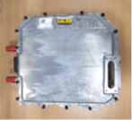
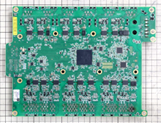
Inverter:Hyundai MOBIS (Kia EV6 GT, Rear) PCB Circuit Analysis Report
 |
 |
 |
| Kia EV6 GT | ||
| Cited: https://www.kia.com/uk/new-cars/ev6-gt/#text_441302445 | Rear Inverter Overview | Rear inverter PCB |
Overview
Kia EV6 GT was released in 2022 by Kia Motors (Kia Corporation), a subsidiary of Hyundai Motors, and this car is the first high-performance BEV (battery electric vehicle).
The range is 423km and the maximum speed is 260km/h.
This report is the detailed circuit analysis report of the rear inverter PCB.
Product characteristics
- Motor is Open-end Winding Motor
- Three types of power modules are used.
(1) ON Semiconductor SiC MOSFET(1200V, Half-Bridge)※
(2) Infineon Si IGBT(1200V, Half-Bridge)
(3) Infineon Si IGBT(1200V, Bi-Directional Switch)
- The car uses a 2-stage motor system.
High efficiency mode driven by (1) and (3), and high output mode in which dual inverters
are configured by (1) and (2). Boost the voltage from 400 V to 800 V using (1) and (2) and a
motor when charging quickly.
- Three NXP MCUs are used.
- Gate Driver is ROHM’s BM60061FV-C (with built-in switching controller).
Module and SiC Structure analysis report and SiC process flow analysis report are available. (Report No:23G-0469-1,2)
Report content
(1) Entire PCB Detailed Circuit Analysis Report (93 pages)
- Teardown
- Component list (Entire PCB)
- Block Diagram and Component level schematic (Entire PCB)
(2) One phase and common circuit PCB Detailed Circuit Analysis Report
- Teardown
- Component list (Partial PCB)
- Block Diagram and Component level schematic (Partial PCB)
Report price
Please contact us for report pricing
If you are interested, please contact us.


